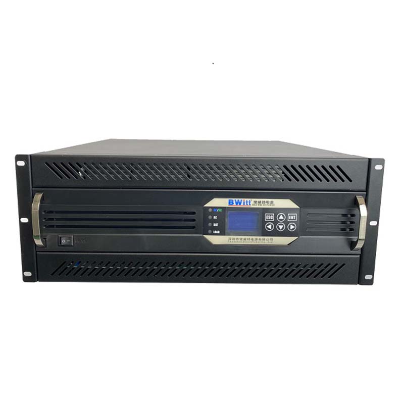
48Vdc &220Vdc Modular parallel inverter Without Battery Pure Sine Wave Inverter 3kw Modular Inverter
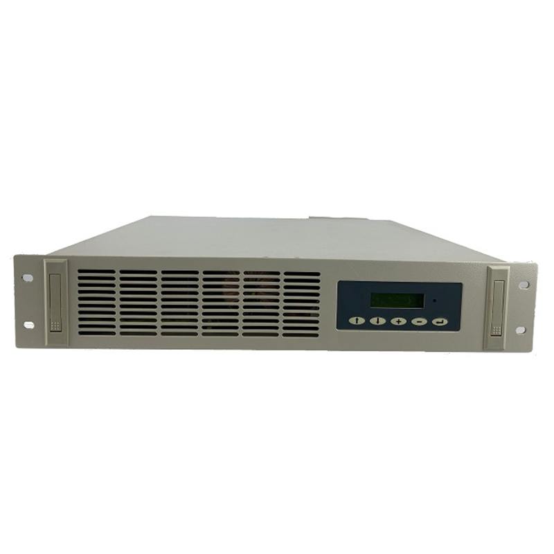
19 Inch 110Vdc & 220Vdc Parallel Inverter Manual user Parallel inverter power supply
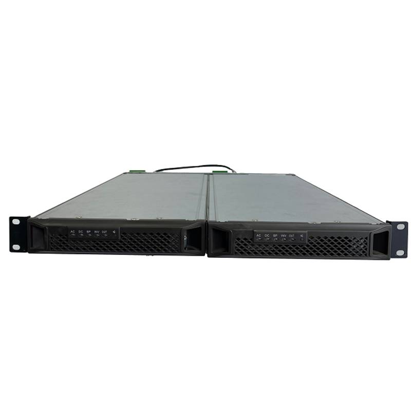
DC 48V 10000 Watt inverter 10KVA pure wave sine power inverter telecom 4U rack mount inverter

Embedded Power System 3u dc 48v 150A switching power supply
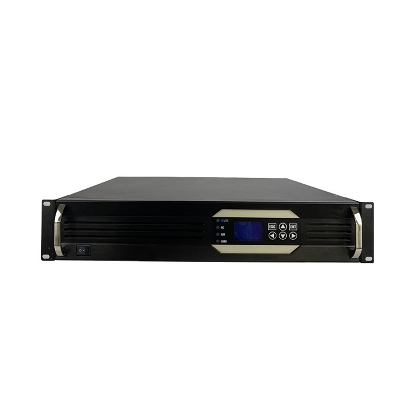
Single-phase Bwitt 48v to AC220v 1000w pure sine wave inverter 1000w inverter with snmp

The parallel inverter consists of two thyristors (T1 and T2), a capacitor, center-tapped transformer and an inductor. The thyristor is used to provide a current path, while the inductor L is used to make the current source constant. These thyristors are controlled on and off by commutation capacitors connected between them.
This complementary commutation method is used to turn the capacitor on and off. Complementary commutation means that when T1 is on, the firing angle is applied to T2 and then the capacitor will turn off T1. What exactly happens is that when T2 is on and the firing angle is applied to T1, T2 will be off due to the capacitor voltage. The output current and voltage are Io and Vo respectively.
It is called a parallel inverter because in the working state, the capacitor C is connected in parallel with the load through the transformer. A shunt inverter is also called a center-tapped transformer inverter because it has a center-tapped transformer between the load and the drive circuit. The function of a transformer is to convert DC into alternating current of the required voltage.
Working of parallel inverters
It operates in simple two modes.
Mode 1
When T1 is triggered, the commutation capacitor will close T2 and the current in the primary winding will flow from A to n. This current in the primary winding will cause the current in the secondary winding to flow clockwise.
Mode 2
By triggering T2, the commutation capacitor will turn off T1. Therefore, the current in the primary winding will flow from B to n and the current in the primary winding will cause the current in the secondary winding to flow counterclockwise.
Advantages of parallel inverters
Several advantages of parallel inverters are as follows:
Stable load voltage: The waveform of the load voltage is independent of the load, and this limitation exists in series inverters. The output voltage of the series inverter depends on the unwanted load.
Cheapest Circuit: The parallel inverter circuit is the cheapest and simplest as it requires only two switches and a center-tapped transformer.
Simple commutation: These inverters use simple Class C commutation operation. Furthermore, the commutation elements do not carry the full load current, which is a very useful aspect of parallel inverters
Few control switches: Compared with H-bridge inverter, only two control switches are needed to complete the operation. The minimum number of switches required for an H-bridge inverter is 4.
Bwitt is the world's leading provider of rack-mounted telecom inverters and modular DC power rectifier system factories.
INQURY9 / F, Building 20 Ericsson Industrial Park, No. 19, Huifeng East 1st Road Zhongkai High-tech Zone, Huizhou City Guangdong Province China