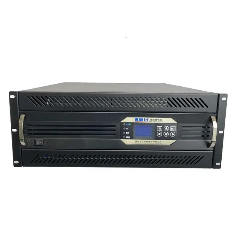
48Vdc &220Vdc Modular parallel inverter Without Battery Pure Sine Wave Inverter 3kw Modular Inverter
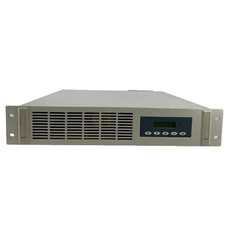
19 Inch 110Vdc & 220Vdc Parallel Inverter Manual user Parallel inverter power supply
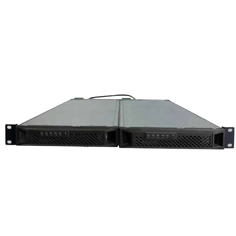
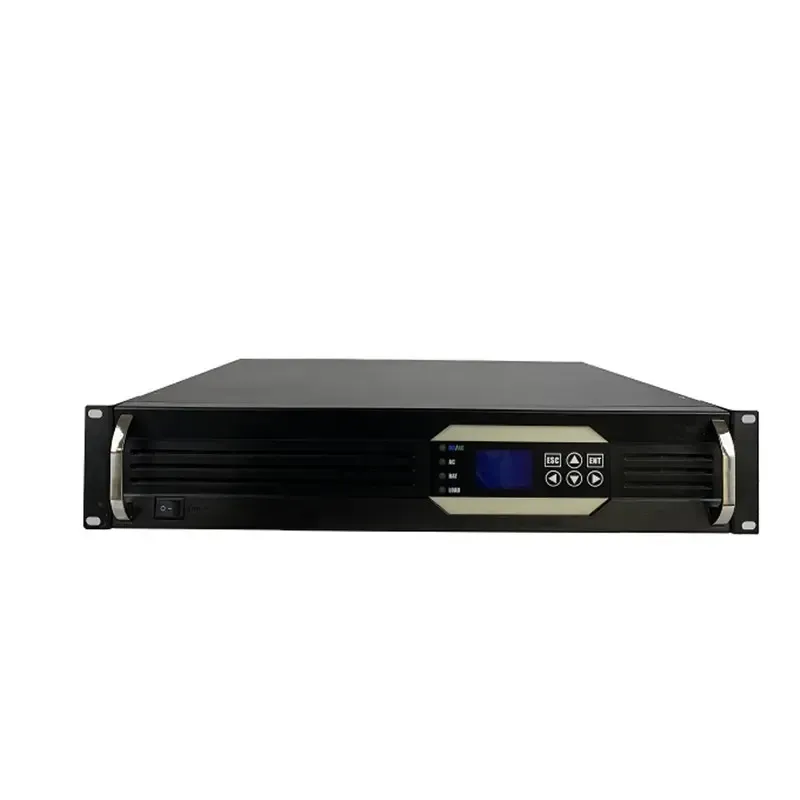
DC 48V 10000 Watt inverter 10KVA pure wave sine power inverter telecom 4U rack mount inverter
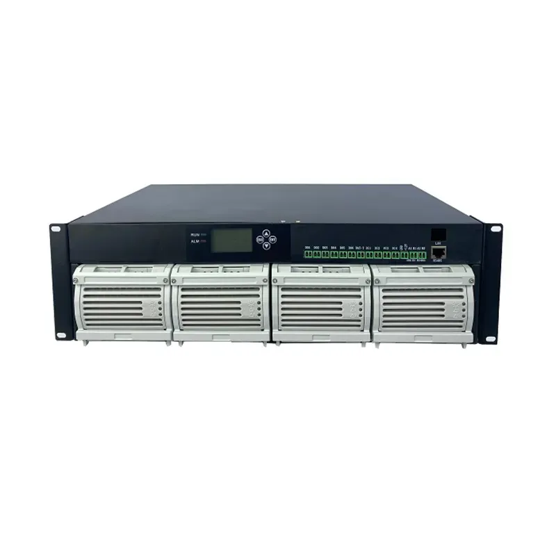
Embedded Power System 3u dc 48v 150A switching power supply
Single-phase Bwitt 48v to AC220v 1000w pure sine wave inverter 1000w inverter with snmp


The working principle of the inverter is to control the operation of the entire system through a control circuit. The inverter circuit completes the function of converting direct current to alternating current, and the filter circuit is used to filter out unwanted signals.
The work of the inverter circuit can also be refined as follows: first, the oscillating circuit converts direct current into alternating current; secondly, the coil boosts the irregular alternating current into square wave alternating current; finally, rectification makes the alternating current into a sine wave alternating current through a square wave.
The working principle of each part of the inverter
1. Input interface part: The input part has 3 signals, 12V DC input VIN, working enable voltage ENB and Panel current control signal DIM. VIN is provided by the Adapter, and the ENB voltage is provided by the MCU on the motherboard, and its value is 0 or 3V. When ENB=0, the inverter does not work, and when ENB=3V, the inverter is in normal working state; while the DIM voltage Provided by the main board, the range of variation is between 0-5V. Different DIM values are fed back to the feedback terminal of the PWM controller. The current provided by the inverter to the load will also be different. The smaller the DIM value, the current output by the inverter. The bigger.
2. Voltage start circuit: When ENB is at high level, it outputs high voltage to light the panel's backlight tube.
3. PWM controller: It has the following functions: internal reference voltage, error amplifier, oscillator and PWM, over-voltage protection, under-voltage protection, short-circuit protection, output transistor.
4. DC conversion: The voltage conversion circuit is composed of MOS switch tube and energy storage inductor. The input pulse is amplified by the push-pull amplifier and then drives the MOS tube to switch, so that the DC voltage can charge and discharge the inductor, so that the other end of the inductor can be Obtain AC voltage.
5. LC oscillation and output circuit: to ensure the 1600V voltage required for the lamp to start, and to reduce the voltage to 800V after the lamp is started.
6. Output voltage feedback: When the load is working, the sampled voltage is fed back to stabilize the voltage output of the inverter
Bwitt is the world's leading provider of rack-mounted telecom inverters and modular DC power rectifier system factories.
INQURY9 / F, Building 20 Erix Science and Technology Industrial Park, 19 East Huifeng Road Zhongkai High-tech Zone, Huizhou City Guangdong Province China